22:
I took the u-boot sources for imx507 from the official repo of the KOBO reader at git://github.com/kobolabs/Kobo-Reader.git cause I was unable to find a working u-boot repository that contains the mx50/imx507. Hey Deutsche Telekom, you should publish something… The u-boot source is located in Kobo-Reader/hw/imx507/u-boot-2009.08.tar.gz. To build the boot-loader you also need a matching tool-chain – happily you can find one also in the KOBO repo – this time in Kobo-Reader/toolchain/gcc-linaro-arm-linux-gnueabihf-4.8-2013.04-20130417_linux.tar.bz2. You could get both archives here (cause the full blown KOBO-Reader-Repo is currently about 3.5G – and you only need these two parts to start):
Copy both archives to a common directory and then:
>tar xzvf u-boot-2009.08.tar.gz
>tar xjvf gcc-linaro-arm-linux-gnueabihf-4.8-2013.04-20130417_linux.tar.bz2
>export PATH=$PATH:/home/devel/projects/tolino_shine/own_uboot/kobo/gcc-linaro-arm-linux-gnueabihf-4.8-2013.04-20130417_linux/bin/
_note 0: replace the exported path with yours!
_note 1a: if you use the files from the git repo – change the name of the used toolchain/gcc-prefix in u-boot-2009.08/build_mddr_256.sh and u-boot-2009.08/build.sh from arm-fsl-gnueabi- to arm-linux-gnueabihf-
_note 1b: The names are already changed in archives linked above.
_note2: For running the build_mddr_256.sh the program dialog (console based dialogs & menus) must be installed on your system.
Now you are ready to build:
>cd u-boot-2009.08/
>./u-boot-2009.08/build_mddr_256.sh
and choose E60610 board, K4X2G323PD – Go! The build process creates a file named u-boot_mddr_256-E60610-K4X2G323PD.bin (just the renamed u-boot.bin) – thats the boot-loader. Easy, huh?
Connect your SD card to your PC – use dmesg to make sure you take the right device for the next steps.
_warning: all data on the SD will be lost!
_note: tested it with 2GB – must not be a SDHC – old cards are working
The bootcode of the CPU expects the code at 0x400 on the SD card. The created image is already padded to fit this needs – so no seeking is needed – just write the image to the card:
#>dd if=u-boot_mddr_256-E60610-K4X2G323PD.bin of=/dev/SDCARD bs=512
The drawback of using the image with padding is, that if you write it to the SD card also the MBR is wiped out – means your partition table is also deleted. For development it is handy to just replace the u-boot and not the 0x400 bytes in front of it – so lets strip the image.
>dd if=u-boot_mddr_256-E60610-K4X2G323PD.bin of=u-boot_mddr_256-E60610-K4X2G323PD.bin.stripped bs=512 skip=2
Writing the stripped image is straight forward – and it keeps the MBR untouched/intact:
#>dd if=u-boot_mddr_256-E60610-K4X2G323PD.bin.stripped of=/dev/SDCARD bs=512 seek=2
_note: before starting developing you should clean the SD card entirely to be save from side-effects caused by old data:
#>dd if=/dev/zero of=/dev/SDCARD bs=512
Plug the card into the shine, connect serial adapter and power on… the first boot-up reveals some other stuff that is needed to boot the shine properly.
MMC read: dev # 0, block # 1023, count 1 partition # 0 ...
1 blocks read: OK
no "hwcfg" bin header
-
MMC read: dev # 0, block # 18431, count 1 partition # 0 ...
1 blocks read: OK
no "logo" bin header
-
MMC read: dev # 0, block # 14335, count 1 partition # 0 ...
1 blocks read: OK
no "waveform" bin header
boot normal : no hwconfig !
_init_tps65185_power(): cannot init without hwconfig !
At the moment I think the tps65185 is the most important – cause without the display powered up we will see nothing. The magic behind the hardware configuration is partly done in freescale/mx50_rdp/ntx_common.c. The array gszNtxBinMagicA contains the magic number (FF F5 AF FF) that is checked within the function _load_ntx_bin_header. The information about the size of the hardware configuration is the location of the magic number + 8 – so if we find the magic number in the image we could easily extract the hardware config of the shine to use it in our own build…
Looking at block 1023 (=0x7fe00) of the backup image for finding the magic number, according to the code…
Magic = 0x7fe00 + 0x200 – 0x10 -> 0x7FFF0 -> Gotcha!
BinSize = Magic + 8 -> 0x7FFF8 = 0x6e -> 110
…strange cause the size of the header is
+0x10 tagNTXHWCFG_HDR
+0x23 tagNTXHWCFG_VAL
———–
0x33
…and only that amount of memory is copied. Strange. But now we could extract the configuration from the backup image of the shine and put it on our SD card.
>dd if=first_16_mb_sd_card.img of=tolino_shine_hw_config.img skip=524272 bs=1 count=67
...
>hexdump -C tolino_shine_hw_config.img
00000000 ff f5 af ff 78 56 34 12 6e 00 00 00 00 00 00 00 |....xV4.n.......|
00000010 48 57 20 43 4f 4e 46 49 47 20 76 31 2e 36 00 26 |HW CONFIG v1.6.&|
00000020 1e 0d 00 00 07 00 00 08 04 06 06 00 00 18 01 00 |................|
00000030 02 00 02 02 07 01 68 02 e4 00 00 02 02 02 00 01 |......h.........|
00000040 05 00 00 |...|
00000043
Now lets write the hardware configuration on the card and check what happens on boot.
#>dd if=tolino_shine_hw_config.img of=/dev/SDCARD seek=524272 bs=1
On boot now we get
....................
Kernel RAM visiable size=255M->255M
init TPS65185 power ...
....................
means the power control for the display is working now 🙂 You can find the complete boot log
here.
_note: have a look at the source files in board/freescale/mx50_rdp – it is a great playground (eg. ntx_hwconfig.h explains what is stored inside the hw config blob)
Next step: adding a kernel and a initrd.
Useful to understand what the heck is done when compiling u-boot for a specific board: freescale IMX50 user guide
19:
I played some days weeks with the Tolino Shine – an ebook reader offered by a consortium of different booksellers and developed by the Deutsche Telekom.
Two results: I’m confused about the idea behind Kafkas „Die Verwandlung“ and the reader is save – in the meaning of „lets enable ADB or gain root the easy way“.
More or less the girls/guys of the Telekom did a good job – only one little hole – but so far no major issue. I explored the shine in hard and software and this post is a sum-up of my findings regarding to this. On some points also some Android background knowledge pops up.
reading the file system
The Tolino Shine exports two drives over USB. One is linked to the internal flash (and named „Mein Tolino“ – with a space in the middle – idiots). The second drive appears only if an micro sd is inserted – as an
unnamed device. I placed files with a fixed name on that drives and tried to access them via the browser by using an URL starting with file://sdcard/… and voilà, that worked well. Its a known issue for old browsers –
see CVE-2010-4804. This hole gives you access to all local files (if rights granted) and could be used to explore the Shine a little… it is possible to read parts of /proc – that gives you access to meminfo, cpuinfo and so on… a lot of useful informations – if you know nothing about a device. Some samples…
proc/partitions
major minor #blocks name
179 0 3872256 mmcblk0
179 1 2263552 mmcblk0p1
179 2 393216 mmcblk0p2
179 3 1 mmcblk0p3
179 4 262144 mmcblk0p4
179 5 524288 mmcblk0p5
179 6 393216 mmcblk0p6
179 8 1933312 mmcblk1
179 9 1933244 mmcblk1p1
/proc/cpuinfo
Processor : ARMv7 Processor rev 5 (v7l)
BogoMIPS : 799.53
Features : swp half thumb fastmult vfp edsp neon vfpv3
CPU implementer : 0x41
CPU architecture: 7
CPU variant : 0x2
CPU part : 0xc08
CPU revision : 5
Hardware : Freescale MX50 Reference Design Platform
Revision : 50011
Serial : 0000000000000000
/system/bin/upgrade_check.sh (cutted)
#!/system/bin/bash -x
i=0
rm /data/no_sd_upgrade
upgrade_check(){
sleep 6
if [ -e /mnt/sdcard/extsd/update.zip ] ; then
echo "---> recovery mode setting ---------------------------------------"
rm /cache/downloadfile*
sync
sync
if [ -e /mnt/sdcard/extsd/update_mark ] ; then
# mv /mnt/sdcard/extsd/update.zip /mnt/sdcard/extsd/update.zip_old
rm /mnt/sdcard/extsd/update.zip
rm /mnt/sdcard/extsd/update_mark
upgrade_check
......
fi
elif [ -e /mnt/sdcard/extsd/waveform.bin ]; then
........
# xiaobo begin of adb_open
# elif [ -e /mnt/sdcard/extsd/adb_open ]; then
# setprop persist.service.adb.enable 1
# sync
# sync
# elif [ -e /mnt/sdcard/extsd/adb_close ]; then
# setprop persist.service.adb.enable 0
# sync
# sync
# xiaobo end of adb open
elif [ -e /mnt/sdcard/extsd/recovery.img ] || [ -e /cache/upgrade/recovery.img ]; then
echo "---> Programming partition RECOVERY ----------------------------------"
......
am start -a android.intent.action.ACTION_REQUEST_SHUTDOWN
fi
}
upgrade_check
It is even possible to read binary files like the init or config.gz – that holds the config for building a kernel… a lot of files – a lot of typing – and it was really a pain to enter all that by hand. So I crafted a page that uses java script to read a local file, encode it into a JSON-string (big overhead – but that is encoding save in every way) and sends it to a server. The page contains a free form text field for entering file names directly, a list of known files (not all are working), and a word book attack that could be run in different locations (the word book was formed by creating permutations from a list single words and separators – not very clever… sorry). You need to place the .php-file on a server the Shine can access – and set
the upload password to something else then the given one – or some strange guys will use your server as some kind of drop box replacement. The upload is limited by the allowed POST-size of your server. Change the encoding of the transmitted data or add multipart file transfer if you like… here the sources, use on your own risk: readout Just copy shine.html and wl.js on the drive name „Mein Tolino“ and point the browser to file://sdcard/shine.html and you should get the following page:
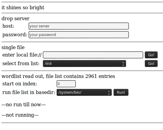
read local files from the shine
Be creative… and report new files you have found on the device. Edit: don’t do it. Continue reading!
the update.zip
After getting a lot of informations from the device I tested its reaction on a file named update.zip by just ‚touching‘ it on the drives. After restarting the reader he tried to install the update-file.
The file was empty – so a seek failed message was printed. A good sign that the shines update/recovery system uses the stock Android verifier code… In these days the long awaited update was made
available – but intercepting the update by sniffing the traffic turned out as ***nearly impossible*** – cause they use an SSL connection for transferring the update file. By sniffing the communication
I made two observations:
- wikipedia.de is called – I think this is the way they check …are we online?!?…
- a suspend-jpg is downloaded from http://www.pageplace.de/media/eink-reader/sleep_screen.jpg – no idea why (conspiracy theory: there is some hidden data in the image…)
But back to the update.zip… For security reasons normally an update-container is signed by the creator. That means that SHA1 was used on the data part to create an unique fingerprint and then the supplier uses a/his private (RSA) key to encrypt the hash. This encrypted hash is then placed as a comment (in a PKCS1.5 container) at the end of the update file (see verifier.cpp – gives an idea how comments are placed in zip files). On startup the device extracts the encrypted hash out of the update.zip, loads the public key (update.zip file res/keys contains an example) stored on the device, decrypts the encrypted hash and compares the result with a SHA1 hash created over the data part of the offered update.zip file… if both hashes are equal the update.zip is accepted. If not an „failed to verify whole-file signature“-error is printed and the device continues to boot. (btw: if you got a „signature is too short“ error the the update contains a comment – but not an PKCS1.5 container)
This information is very important cause most articles I found about repacking and signing update.zip files do not outline that the signature used for checking authenticity and validity is based on a/some public key(s) stored on the device. To use self signed update files the recovery program must be replaced by a version that ignores the signature check or a new public key (for a known private key) must be installed on the device. Both ways are not open for now. So if you change something within the update file you are out of luck.
If you are going to create your own certificates for signing update-files, remember to use 3 as exponent for the RSA (…at least for the Tolino – if I got it right e was changed back to 65537 in later Android versions).
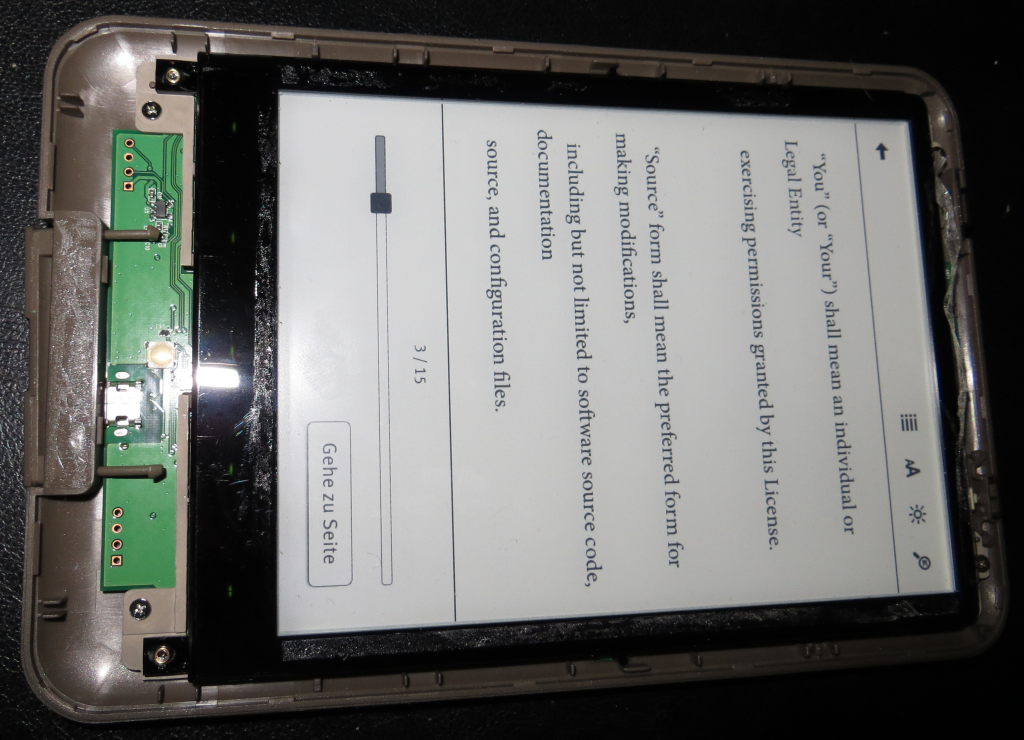
According to the license pdf contained in the archive the Shine is updated to Android 2.3.4 – the license file contained in firmware 1.0.1 shows 2.3.3 as the used Android version.
shiny kernel
A nice guy (thank you, Hajo) shared a link to the kernel sources of the Tolino Shine. I think they were published by accident cause the download location is a formerly unprotected WordPress upload directory… The Shine uses a 2.6.35.3 Kernel – a diff against the sources from kernel.org returns the changes made for the Shine… mainly patches from freescale to support the MX-series, the Android parts and some additions made by the Shine firmware developers (Joseph? , Angela?, Daniel?) . You can compile and start it using qemu – but thats all – a booting kernel – nothing special.
at the end…
I was a little frustrated …I opened the shine – looking for a JTAG connector or at least a serial port. It was not that easy to open the cover cause the display frame is glued to the upper half of the enclosure using double sided tape… but after some sweating it was done. The entire board – the PCB and the display – is mounted to the bottom cover with 4 screws.
- Tolino board mounted on backcover
After removing them I was able to pull out the whole electronic body – nice.
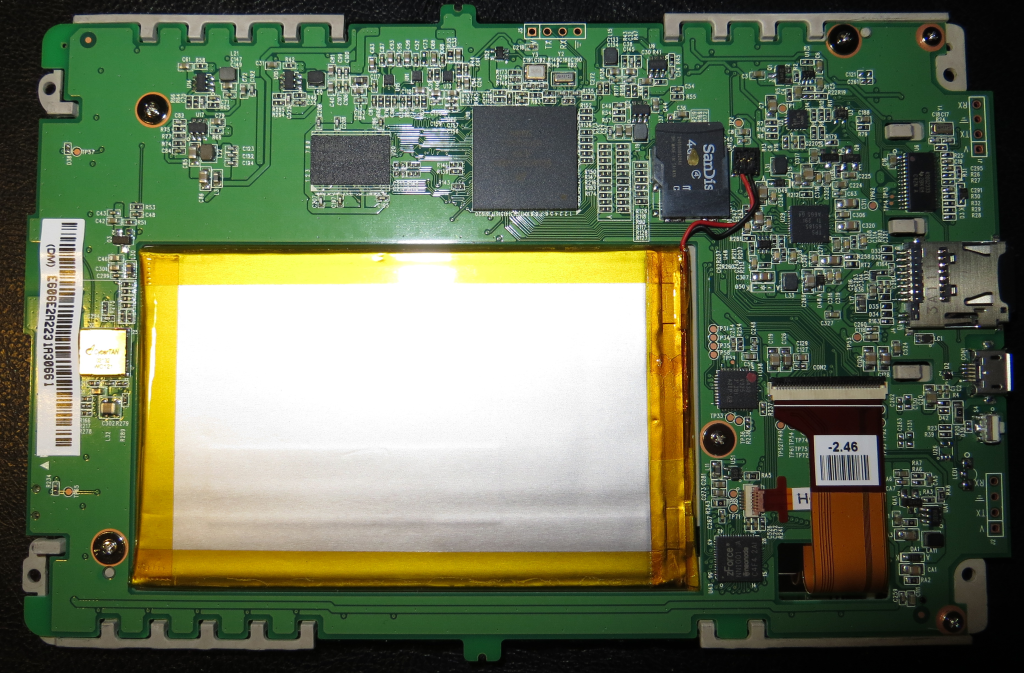
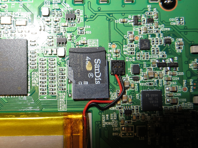
The first thing that catches my attention was the micro SD located on the back of the board… wow, what a find. I did a backup of the whole card (after running the restore to factory process) – you can find the image here:
Instead of using a dedicated NAND flash chip an SD card is used to store all persistent data… what the heck… that means: you can replace the complete system image without the hazel of a soldered NAND chip / JTAGing cause you can write the system to the SD an try it out… and there should be no way to brick the device cause you could replace the (persistent) memory easily… and I was looking for a JTAG port… happiness. The partition table of the internal SD card as shown by parted and enriched with infos from recovery.fstab:
Number  Start   End     Size    Type      File system  Flags
1      15.7MB  2334MB  2318MB  primary   fat32                      /sdcard vfat /dev/block/mmcblk0p1   "Mein Tolino"
2      2334MB  2736MB  403MB   primary   ext4                       /system ext4 /dev/block/mmcblk0p2
3      2736MB  3679MB  943MB   extended
5      2737MB  3274MB  537MB   logical   ext4                       /data ext4 /dev/block/mmcblk0p5
6      3275MB  3678MB  403MB   logical   ext4                       /cache ext4 /dev/block/mmcblk0p6
4      3679MB  3947MB  268MB   primary   ext4                       recovery
There are 15 megs of space in front of the first partition – here my findings:
0x000000 - 0x0001bf filled with 0 - means: no boot loader
0x0001c0 - 0x0001ff partition table (ends with 55aa)
0x000200 - 0x00020a serial number (device type)
0x00020b            just a colon
0x00020c - 0x00022b another serial/a hash? (32 byte)
0x000400 - 0x02695f uboot (contains also the recovery)
0x07fff0 - 0x080035 HW Config v 1.6 - version string?
0x0e0002 - 0x0e07ff binary blubber
0x0f0002 - 0x0f07ff binary blubber
0x0ffff0 - 0x0fffff binary blubber
0x100000 - 0x10003f uboot header
0x100040 - 0x43122e kernel
0x5ffff0 - 0x6236ff initramfs
0x6ffff0 - 0x81658e binary blubber...
After browsing the endless hex-file and writing the fun down I found recovery:/system/bin/upgrade.sh – it shows a partly different partition scheme – but contains also useful informations.
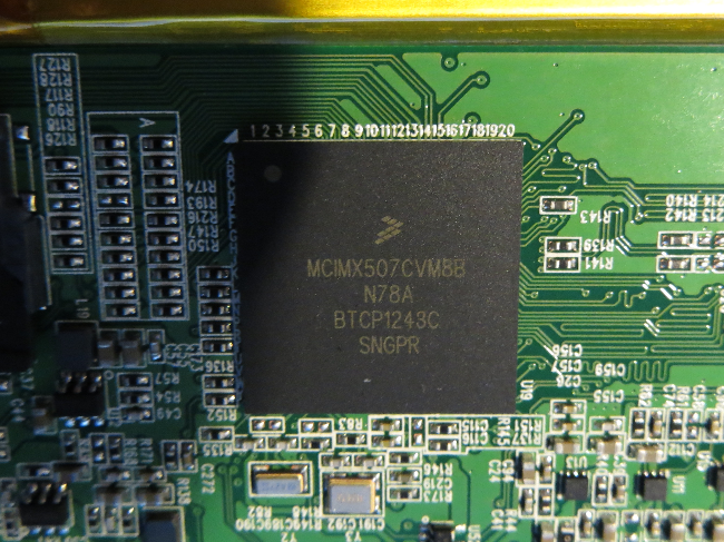
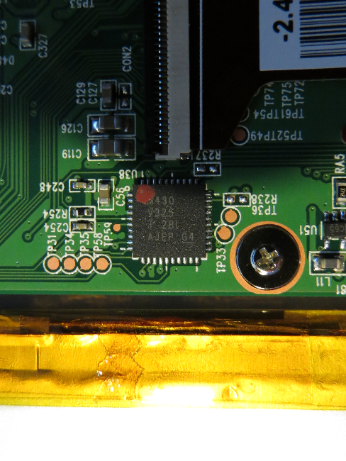
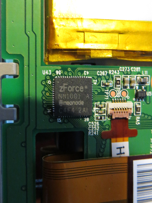
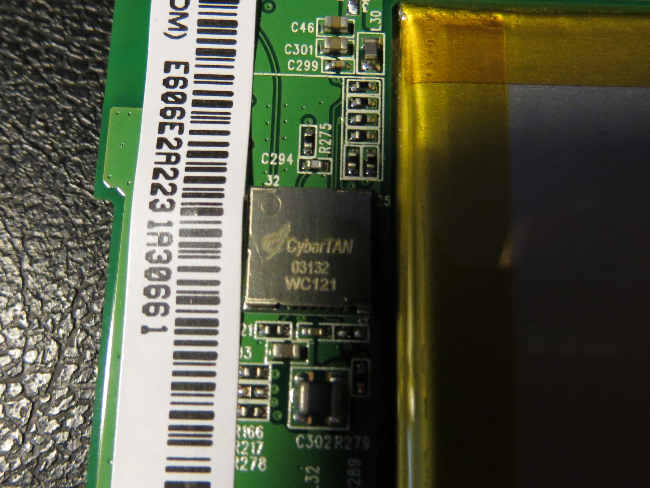
shiny hardware
Here comes a list of the chips I found on the board:
| plate |
function |
manufacturer |
data sheet/info |
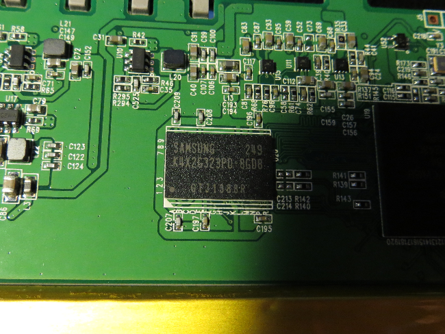
| K4X2G323PD8GD8 |
DRAM 64Mx32 = 256 MB, 800 Mhz, 1.8V |
SAMSUNG |
|
| MCIMX507CVM8B |
Cortex A8, up to 800 Mhz |
Freescale |
www.freescale.com/webapp/sps/site/prod_summary.jsp?code=i.MX507 |
| zForce NN1001 |
optical touch controller |
neonode & TI |
|
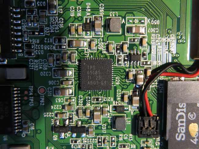
| TPS 65185 |
eInk power supply |
TI |
http://www.ti.com/product/tps65185 |
| 430G2333 |
micro controller (reading battery state?) |
TI |
http://www.ti.com/product/msp430g2333 |
| 430V325 |
micro controller (charging?) |
TI |
http://www.ti.com/product/msp430p325 |
| wc121 |
single chip WLAN module |
cybertan |
http://www.cybertan.com.tw/products/WC121.html |
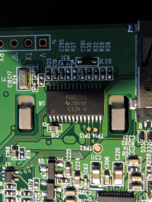
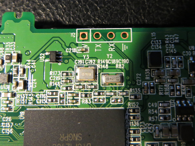
serial reader
There are 3 serial ports on the board. The one next to the CPU (right side of the board) is … the serial port that is connected to the CPU. Using a proper interface with 3.3V signal level and a terminal program running at 115200 8N1 you can sniff the boot messages of u-boot and the kernel. Don’t forget to cross RX and TX and again: use 3.3V signal levels!
U-Boot 2009.08 ( 1月 25 2013 - 15:04:09)
-
CPU: Freescale i.MX50 family 1.1V at 800 MHz
mx50 pll1: 800MHz
mx50 pll2: 400MHz
mx50 pll3: 216MHz
ipg clock : 66666666Hz
ipg per clock : 66666666Hz
uart clock : 24000000Hz
ahb clock : 133333333Hz
axi_a clock : 400000000Hz
axi_b clock : 200000000Hz
weim_clock : 100000000Hz
ddr clock : 200000000Hz
esdhc1 clock : 80000000Hz
esdhc2 clock : 80000000Hz
esdhc3 clock : 80000000Hz
esdhc4 clock : 80000000Hz
Board: MX50 RDP board
Boot Reason: [POR]
Boot Device: SD
I2C: ready
DRAM: 256 MB
......................
MMC read: dev # 0, block # 14336, count 2228 partition # 0 ...
2228 blocks read: OK
Kernel RAM visiable size=254M->254M
Detecting HOME+POWER key for recovery ...
Hit any key to stop autoboot: 0
-
MMC read: dev # 0, block # 2048, count 8192 partition # 0 ...
8192 blocks read: OK
-
MMC read: dev # 0, block # 12288, count 768 partition # 0 ...
768 blocks read: OK
## Booting kernel from Legacy Image at 70800000 ...
Image Name: Linux-2.6.35.3-hg9facadc85de9-di
Created: 2013-01-25 7:01:22 UTC
Image Type: ARM Linux Kernel Image (uncompressed)
Data Size: 3346940 Bytes = 3.2 MB
Load Address: 70008000
Entry Point: 70008000
Verifying Checksum ... OK
## Loading init Ramdisk from Legacy Image at 70d00000 ...
Image Name: ntxinitramfs
Created: 2013-02-05 5:38:45 UTC
Image Type: ARM Linux RAMDisk Image (uncompressed)
Data Size: 145089 Bytes = 141.7 kB
Load Address: 70308000
Entry Point: 70308000
Verifying Checksum ... OK
Loading Kernel Image ... OK
OK
...................................
Starting kernel ...
Uncompressing Linux... done, booting the kernel.
Initializing cgroup subsys cpu
Linux version 2.6.35.3-hg9facadc85de9-dirty (antony@antony-desktop) (gcc version 4.4.3 (GCC) ) #168 PREEMPT Fri Jan 25 15:01:19 CST 2013
CPU: ARMv7 Processor [412fc085] revision 5 (ARMv7), cr=10c53c7f
...................................
Of course – you can interrupt the boot process by pressing a key.. here comes the output of printenv and bdinfo:
eBR-1A # printenv
bootdelay=1
baudrate=115200
loadaddr=0x70800000
netdev=eth0
ethprime=FEC0
uboot=u-boot.bin
kernel=uImage
nfsroot=/opt/eldk/arm
bootargs_base=setenv bootargs console=ttymxc0,115200
bootargs_nfs=setenv bootargs ${bootargs} root=/dev/nfs ip=dhcp nfsroot=${serverip}:${nfsroot},v3,tcp
bootcmd_net=run bootargs_base bootargs_nfs; tftpboot ${loadaddr} ${kernel}; bootm
bootargs_mmc=setenv bootargs ${bootargs} ip=dhcp root=/dev/mmcblk0p2 rootwait
bootcmd_mmc=run bootargs_base bootargs_mmc; bootm
rd_loadaddr=0x70D00000
bootcmd_SD=mmc read 0 ${loadaddr} 0x800 0x2000; mmc read 0 ${rd_loadaddr} 0x3000 0x300;
bootcmd=run bootcmd_SD; bootm ${loadaddr} ${rd_loadaddr}
bootargs=console=ttymxc0 init=/init androidboot.console=ttymxc0 keypad video=mxc_elcdif_fb:off calibration
stdin=serial
stdout=serial
stderr=serial
-
eBR-1A # bdinfo
arch_number = 0x00000BAC
env_t       = 0x00000000
boot_params = 0x70000100
DRAM bank   = 0x00000000
-> start    = 0x70000000
-> size     = 0x10000000
baudrate    = 115200 bps
You can download the complete bootlog here: tolino_shine_boot_log.txt
After booting you are put to a bash shell but the console is cluttered by a continuously stream of some redraw informations and the logging of temperature state of the display voltage controller. If you are lucky you can get some clean output…
bash-3.2# ps
USER PID PPID VSIZE RSS WCHAN PC NAME
root 1 0 324 188 800ec05c 0000875c S /init
root 2 0 0 0 800823d8 00000000 S kthreadd
root 3 2 0 0 80071a24 00000000 S ksoftirqd/0
root 4 2 0 0 8007ec3c 00000000 S events/0
root 5 2 0 0 8007ec3c 00000000 S khelper
root 8 2 0 0 800890f0 00000000 S async/mgr
root 9 2 0 0 8007ec3c 00000000 S pm
root 12 2 0 0 8007ec3c 00000000 S suspend
root 76 2 0 0 80057a2c 00000000 S usb_wakeup thre
root 77 2 0 0 80057a2c 00000000 S usb_wakeup thre
root 234 2 0 0 800bb414 00000000 S sync_supers
root 236 2 0 0 800bbef4 00000000 S bdi-default
root 238 2 0 0 8007ec3c 00000000 S kblockd/0
root 252 2 0 0 8007ec3c 00000000 S mxc_spi.2
root 259 2 0 0 8007ec3c 00000000 S otg_switch/0
root 265 2 0 0 8029d5c8 00000000 S khubd
root 282 2 0 0 8007ec3c 00000000 S kmmcd
root 312 2 0 0 8031c4d4 00000000 S pmic-event-thre
root 336 2 0 0 8007ec3c 00000000 S rpciod/0
root 345 1 0 0 80051524 00000000 D swapper
root 350 2 0 0 8007ec3c 00000000 S zq_calib
root 356 2 0 0 800b5abc 00000000 S kswapd0
root 404 2 0 0 8007ec3c 00000000 S aio/0
root 414 2 0 0 8007ec3c 00000000 S nfsiod
root 418 2 0 0 8007ec3c 00000000 S crypto/0
root 446 2 0 0 8007ec3c 00000000 S submit/0
root 457 2 0 0 8007ec3c 00000000 S tps65185_PWRGOO
root 459 2 0 0 8007ec3c 00000000 S tps65185_INT/0
root 1039 2 0 0 802346f8 00000000 S kapmd
root 1105 2 0 0 802c4260 00000000 S file-storage
root 1149 2 0 0 8007ec3c 00000000 S kstriped
root 1154 2 0 0 8007ec3c 00000000 S kconservative/0
root 1157 2 0 0 8007ec3c 00000000 S mxc_chg
root 1158 2 0 0 8007ec3c 00000000 S mc13892_battery
root 1165 2 0 0 8007ec3c 00000000 S esdhc_wq/0
root 1170 2 0 0 8007ec3c 00000000 S esdhc_wq/0
root 1172 2 0 0 8007ec3c 00000000 S esdhc_wq/0
root 1182 2 0 0 8007ec3c 00000000 S usbhid_resumer
root 1185 2 0 0 8007ec3c 00000000 S binder
root 1217 2 0 0 8007ec3c 00000000 S l2cap
root 1218 2 0 0 80459624 00000000 S krfcommd
root 1226 1 300 156 800ec05c 0000875c S /sbin/ueventd
root 1243 2 0 0 80336e9c 00000000 S mmcqd
root 1309 446 0 0 8006ff84 00000000 Z submit/0
root 2013 2 0 0 80336e9c 00000000 S mmcqd
root 2015 2 0 0 8015c29c 00000000 S jbd2/mmcblk0p2-
root 2018 2 0 0 8007ec3c 00000000 S ext4-dio-unwrit
root 2019 2 0 0 800fbf4c 00000000 S flush-179:0
root 2020 2 0 0 8015c29c 00000000 S jbd2/mmcblk0p5-
root 2021 2 0 0 8007ec3c 00000000 S ext4-dio-unwrit
root 2022 2 0 0 8015c29c 00000000 S jbd2/mmcblk0p6-
root 2023 2 0 0 8007ec3c 00000000 S ext4-dio-unwrit
root 2024 1 1428 780 8006f710 000a8fa8 S /system/bin/bash
system 2025 1 816 256 8034b580 6fd0b6fc S /system/bin/servicemanager
root 2026 1 3868 588 ffffffff 6fd0bdac S /system/bin/vold
root 2027 1 3844 560 ffffffff 6fd0bdac S /system/bin/netd
root 2028 1 820 324 800ec05c 6fd0b844 S /system/bin/dispd
root 2029 1 676 260 803834dc 6fd0c0cc S /system/bin/debuggerd
root 2030 1 99812 27668 800ec05c 6fd0b844 S zygote
media 2031 1 17216 4212 ffffffff 6fd0b6fc S /system/bin/mediaserver
root 2032 1 824 316 804057bc 6fd0b45c S /system/bin/installd
keystore 2033 1 1752 428 803834dc 6fd0c0cc S /system/bin/keystore
shell 2036 1 3400 164 ffffffff 00008294 S /sbin/adbd
system 2088 2030 165876 36432 ffffffff 6fd0b6fc S system_server
app_3 2140 2030 116008 20024 ffffffff 6fd0c51c S com.android.inputmethod.latin
system 2146 2030 108160 14940 ffffffff 6fd0c51c S ntx.power
system 2152 2030 113392 24008 ffffffff 6fd0c51c S com.android.systemui
system 2153 2030 138684 35756 ffffffff 6fd0c51c S de.telekom.epub
app_6 2192 2030 112424 19224 ffffffff 6fd0c51c S android.process.acore
app_4 2220 2030 111196 17944 ffffffff 6fd0c51c S android.process.media
app_5 2230 2030 108752 16912 ffffffff 6fd0c51c S com.android.providers.calendar
root 2250 2 0 0 800fbf4c 00000000 S flush-179:8
root 2257 2024 904 316 00000000 6fd0b45c R ps
And btw – about „rooting“ that device:
bash-3.2# id
uid=0(root) gid=1007(log)
I also tried to get some data from the remaining serial ports – but nothing happens here. Maybe they use a protocol based on polling or they are not for reading data bur for programming the two MSP430 processors… follow the traces and tell us if you found something great…
ADB
I made some changes on the SD card to enable ADB by activating some uncommented lines in /system/bin/upgrade_check.sh. Remember – this file was one of my first findings in the beginning of the journey. It gives me some (late) satisfaction to use that file (even if I had to open the Shine for it – and of curse, there are other ways to do that – just remove the disabled flag for the ADB service…)
# xiaobo begin of adb_open
elif [ -e /mnt/sdcard/extsd/adb_open ]; then
setprop persist.service.adb.enable 1
sync
sync
elif [ -e /mnt/sdcard/extsd/adb_close ]; then
setprop persist.service.adb.enable 0
sync
sync
xiaobo end of adb open
After that I touched a file named adb_open to /sdcard/extsd. If you had a look at the boot-log you already found a line containing the following:
warning: `adbd' uses 32-bit capabilities (legacy support in use)
enabling adb
I can’t give you any information about using ADB in windows. But if you are running Linux you are fine eg. under Ubuntu sudo apt-get install android-tools-adb will provide you with the needed tool. If not and your distro does not offer a package that contains ADB go and download the right part from the Android SDK. Good luck.
If you have installed ADB the remaining part is straight forward:
# get the vendor id from syslog (maybe dmesg | grep idVendor): idVendor=1f85 then...
#> echo 'SUBSYSTEM=="usb", ATTR{idVendor}=="1f85", MODE="0666", GROUP="plugdev"' >> /etc/udev/rules.d/51-android.rules
#> mkdir ~/.android/
#> echo 0x1f85 > ~/.android/adb_usb.ini
#> adb server-start
#> adb devices
-
List of devices attached
20030394 device
-
#> adb shell
$ ls
config
cache
sdcard
acct
mnt
vendor
d
etc
sys
init.rc
ueventd.rc
default.prop
sbin
init.goldfish.rc
ueventd.freescale.rc
system
ueventd.goldfish.rc
data
init
proc
init.freescale.rc
root
dev
....
The rest is up to you. With ADB enabled you could close the enclosure and use USB for communication… just use the serial line to remove permission restrictions before:)
next steps
Exploring the Tolino Shine was fun. I ended up with a device that was opened… not really rooted by using some software – some special kind of escalation. But looking for a JTAG interface and finding an easy to change SD card is… win. Having ADB and serial connection now is nothing to be proud of – it was inside the device all the time. And to be honest: I feel a little bit sad that I was not able to achieve at least the working ADB without opening the device. Now some scripts have to be done to enable ADB all the time and remove all permission restrictions on that device (and: publish new SD images!). Maybe someone could change the Public Key (one is located in the recovery partition – just look for key, use the informations about creating keys and the key file out of this ) in the image by on of a well known keypair… a lot of stuff if you like to continue in a eco system called „Tolino Shine“. For me the device is now just an easy to change and powerful system with a excellent touch screen, a serial port and more or less space inside the enclosure to add new hardware. So there are two big possibilities to continue on:
- analyzing the system by looking at the whole system description – in hard- and software, find the weak point and root the device without opening it
- create your own system running on the shines hardware
The latter one is the way I choose – the goal is a sd card image that holds all the stuff to run the shine as piratebox… But with the announcement of new Tolino hardware for the end of 2013 the price should go down… more Shines, more developers… Lets see what happens. Good luck!
relevant links
hardware:
http://www.freescale.com/webapp/sps/site/prod_summary.jsp?code=IMX50EVK
ARM knowledege base:
http://infocenter.arm.com/help/index.jsp?topic=/com.arm.doc.faqs/
Porting kernel to arm:
http://www.linux-arm.org/pub/LinuxKernel/WebHome/aleph-porting.pdf
freescale downloads:
http://git.freescale.com/git/
ARM toolchain:
https://wiki.linaro.org/Resources/ToolchainInstall-10/4.4
http://www.linaro.org/downloads/
https://github.com/AdiPat/Android_Toolchains
uboot:
http://www.compulab.co.il/workspace/mediawiki/index.php5/U-Boot:_Images
http://balau82.wordpress.com/2010/03/10/u-boot-for-arm-on-qemu/
qemu – arm:
http://www.linuxforu.com/2011/06/qemu-for-embedded-systems-development-part-1/
http://wiki.qemu.org/Download
http://balau82.wordpress.com/2010/03/22/compiling-linux-kernel-for-qemu-arm-emulator/
http://mmmyddd.freeshell.net/wiki/embed/linuxonarmonqemu.html
http://qemu.weilnetz.de/qemu-doc.html#ARM-System-emulator
https://wiki.edubuntu.org/ARM/RootfsFromScratch/QemuDebootstrap
problems with ARM on qemu:
https://community.freescale.com/thread/281256
good intro about using gdb with qemu to debug a running system:
http://files.meetup.com/1590495/debugging-with-qemu.pdf
kernel debug:
https://www.kernel.org/doc/htmldocs/kgdb/EnableKGDB.html
http://elinux.org/Debugging_by_printing#Debugging_early_boot_problems
gdb kernel stub:
http://wiki.osdev.org/GDB
android ndk download:
http://developer.android.com/tools/sdk/ndk/index.html
.apk – run and reverse:
http://stackoverflow.com/questions/4512458/androidhow-to-run-apk-file-on-emulator
https://code.google.com/p/android-apktool/
android security:
http://www.ibm.com/developerworks/library/x-androidsecurity/
android filesystem overview:
http://anantshri.info/andro/file_system.html
android – relevant sources:
https://android.googlesource.com/platform/bootable/recovery/+/master/bootloader.cpp
https://android.googlesource.com/platform/bootable/recovery/+/master/verifier.cpp
https://android.googlesource.com/platform/bootable/recovery/+/master/install.cpp
update.zip:
http://images.thalia.de/md2/ereader/update/update.zip
http://www.sslshopper.com/certificate-decoder.html
http://www.londatiga.net/it/how-to-sign-apk-zip-files/
http://developer.android.com/tools/publishing/app-signing.html
keys & co – tools, infos:
https://raw.github.com/cgjones/android-system-core/master/libmincrypt/tools/DumpPublicKey.java
http://www.bouncycastle.org/latest_releases.html
http://en.wikipedia.org/wiki/RSA_%28algorithm%29
uRamdisk, initrd & co:
http://forum.xda-developers.com/showthread.php?t=1477845
http://www.glomationinc.com/doc/HowToEditRAMDisk.PDF
http://www.isysop.com/unpacking-and-repacking-u-boot-uimage-files/
http://www.unixboard.de/vb3/showthread.php?5913-initrd-img-bearbeiten
CVE:
http://www.cvedetails.com/product/19997/Google-Android.html?vendor_id=1224
http://www.cvedetails.com/cve/CVE-2010-4804/
http://cve.mitre.org/cgi-bin/cvename.cgi?name=CVE-2010-1807
http://thomascannon.net/blog/2010/11/android-data-stealing-vulnerability/
other readers but related:
http://pastie.org/pastes/6112039
13:
Our cellar and our briefcase was „emptied“ by some strangers and the main door has fresh marks of a crowbar… The criminal statistic for housebreaking has climbed a new peak – time to get paranoid. Since I don’t like psycho pharmacy I created a little circuit around a ATtiny45 that is able to handle the following external sensors and actors – to act as a door alarm system:
- hidden arm/disarm switch – just use the door bell to get a knocking sequence
- hall sensor, triggered by a little magnet (3 mm diameter, 4 mm long) embedded in our wooden door
- red/green LED to signal the state of the alarm system
- switch a external horn on/off to create a fu*** (nny) loud noise
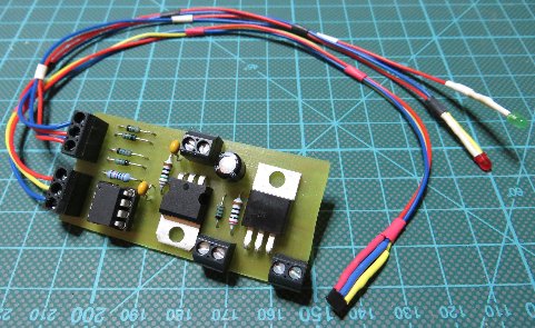
To run the system I decided to take some juice from the door opener. He offers a 12V AC line – so I used an recycled bridge rectifier and some capacitors to create a rudimentary 12V DC source…
bridge rectifier
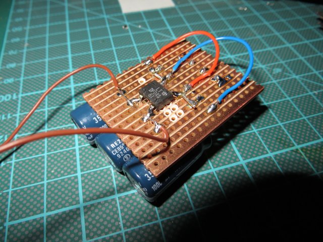
The controller board was created with Eagle in THT old school style (schematic + board: dooralarm – yes, I increased the diameter of the drill holes for the resistors and capacitors a little…). The brain of the board is an ATtiny45. The hall sensors part is played by a TLE4905L. It is quite easy to use – just connect Q to an input of the uC and use the internal pull up to create a clean logic 1 if no magnetic field is applied to the sensor – that’s all. In conjunction with that little neodymium cylinder magnet I got a detection range of 5..7 mm – far enough to sense the state of the door safely.
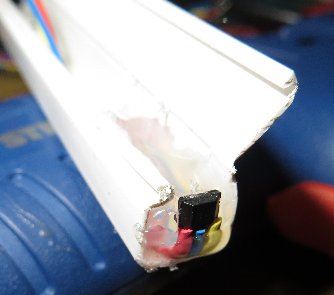
hot glue to keeps the sensor in place
The disarm hall sensor is placed inside the housing of the controller board. Just place a magnet on the housing – the alarm state is overridden – and the horn is off. The horn (piezo, 120dB@12V/0.2A) is controlled by a BUZ11 so I could extend the system easily by heavier loads.
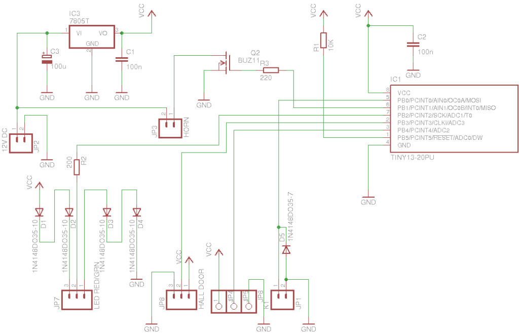
schematic of the controller board
As I run out of pins (I kept the reset pin for easy programming) I used that funny way of driving the status LEDs with only one port pin… so don’t worry about that.
controller board
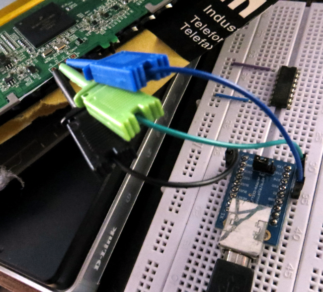
By accident I stumbled over the AD-2000M – a RFID/keypad door opener panel. I found a seller here in Germany (reduces shipping time a lot) that sold the device for a reasonable price: including 10 key chain tags and shipping only 12 € – nice. The devices arrived 2 days later – and I tried to understand the manual arrrgh! … in short:
- you can have 3 types of users
- activate with RFID tag only
- activate with RFID tag + 6 digit PIN
- 6 digit PIN only
- every user is identified by a unique 4 digit user id
- a user id can only be used with one type of user
(its not possible to use the same user id for a user with card or PIN only access)
The AD-2000M Rev. 3 works according to the following state machine:
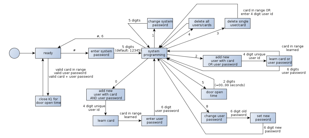
programming states ad2000-m rev 3.0
The AD2000-M is able to detect the RFID tags through the (wooden) door – a nice replacement for the hidden arm/disarm switch formed by bell knocking… good. The controller board also fits inside the housing of the device so no further enclosing is needed. Very good. During the first tests of the setup I recognized that the 7805 inside the AD2000-M creates an enormous heat. Bad. Reason: even in the „ready“- state the device draws 60mA (for what?!?) – makes ~0.4W power dissipation over the 7805… way to much over the time. I also disliked the idea having 2 7805 sitting around and wasting energy. The moment to use a very nice drop in replacement from TI: the PTH08080W. It comes in form of a ready to use wide input range step down regulator – just kick out the 7805, solder a resistor to the module (to select the desired output voltage – ~350 Ohm for 5V output) – and thats it… many thanks to TI for the samples! ***advertisement finished***
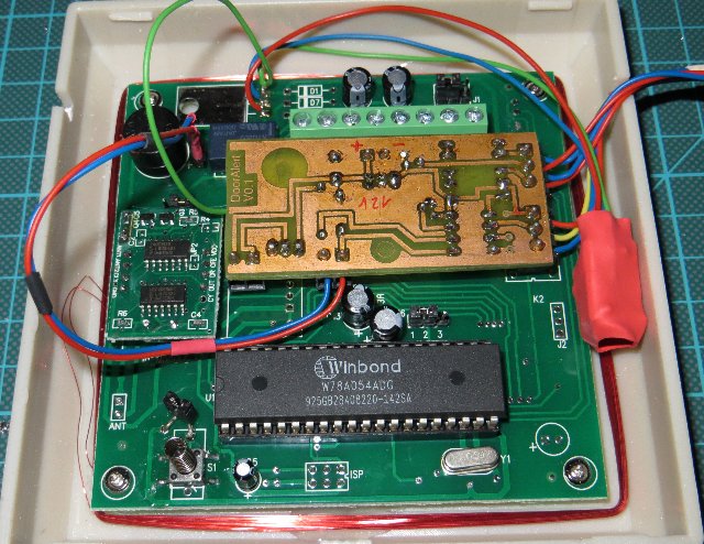
controller inside the ad2000-m
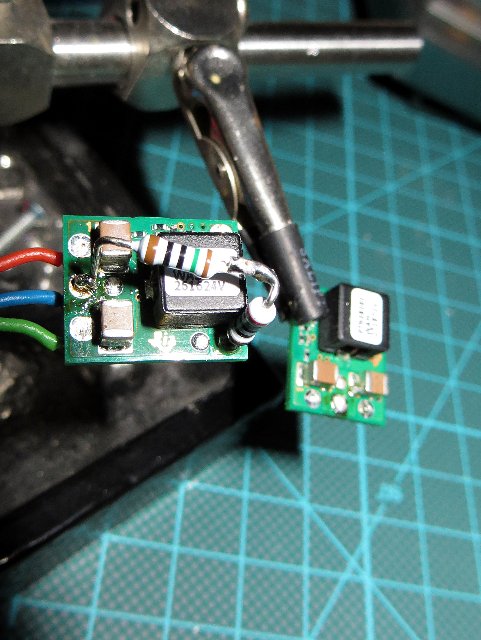
PTH08080W – drop in replacement
Note 1: the little jumper soldered to the via holes on the left side of the controller prevents me from the cover open alarm
Note 2: the shrink wire covered red blob contains the PTH08080W
Note 3: I used the two vias on the left side of the relay to connect my switch input (see schematic + board – input K1 +/-). The relay is switched on if the door opener is activated. I simply detect the state of the relay – voila – an RFID arm/disarm switch.
The alarm system is based on a simple state machine. If the system is armed by using a known identification token (RFID, PIN) and the door is opened a short sequence of pulses is given. After that, the horn sound continuously for 30, 45, 2x 60 seconds with little breaks. Finally the horn is deactivated – to protect my neighbors from screaming sounds during my holidays… (for easier drawing the „move from trigger-state-to-disarm“ transition is not shown).
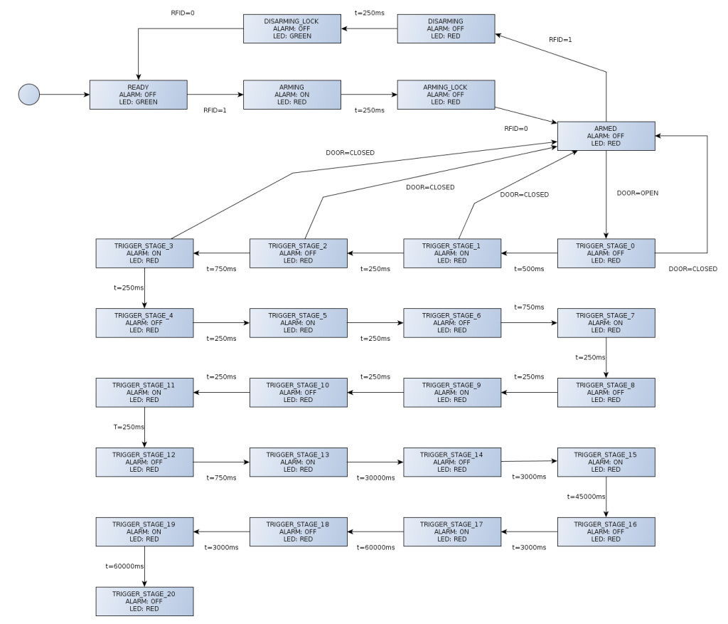
states of the alarm system
The __LOCK-states are used for filtering bouncing contacts of the relay. To prevent a complete alarm cycle caused by a „hard knock“ against the door the system reverts to the armed state if the door is closed within the first 1.5 seconds. Programming the controller was straight forward… I just translated the state machine from the picture above. Since the code deals with a security device no optimization was applied – just easy to read and maintain code (dooralarm – firmware). Sorry! for not posting any picture of the finished system. But that would be like posting my bank cards PIN… That’s it.
26:
I quit my last job where I had access to great labs – including the one for making PCBs the easy way (yeah, they have all the nice/expensive tools from Bungard … and a CNC miller/cutter). So now I had to decide how to setup the needed infrastructure for making PCBs@home. Here are some of the results.
For putting the layout on the PCB I decided to use the direct toner transfer method with a modified laminator like described here. Cause of the chicken-and-egg-problem I used an Arduino to control the heater instead of a dedicated board (what I create after the setup for making PCBs is done so I can create more boards…). It works very well – thanks to all the folks that invented/improved that technology.
Since I do all the fun at home I choose sodium per sulfate as etchant – its a clean and safe solution. First I thought about buying a commercial etching machine. But after some reading it turns out that all the inexpensive and/or cheap machines are … to expensive. I moved to the hardware store and got all I needed for less then 50 euro:
- round glass vase, 25 cm hight, 9 cm diameter ~ 5 €
- aquarium heater, 100 W – 20 €
- aquarium membrane air pump ~ 10 €
- fizzy stone ~ 2 €
- 2 m silicone tube ~ 2 €
- return valve ~ 3 €
- a sheet of 4 mm acrylic glass (30 cm x 20 cm) ~ 5 €
- pack of 4 cupping vessels ~ 2 €
I also ordered a 24 cm long tee thermometer that goes till 110 degree Celsius for ~8 €. But a simple 2-euro window thermometer with a range from -x..50 degree Celsius also does that job. But the tee thermometer looks better. Much!
First I created an holder for the fizzy stone by heating a small strip (5 cm x 10 cm) of the acrylic glass with my kitchen gas torch in the middle and bend it by 90 degrees. Two holes later a cupping vessel and the stone are mounted and put in place on the ground of the vase:

fizzy stone holder
Cause of the air bubbles the etchant could spray out of the upper end. A quadratic cover of 10×10 cm acrylic glass makes a good seal. To keep it in place I glued a smaller piece (5.5×5.5 cm) that fits (nearly) the inner diameter of the glass vase in the center of the larger one. The width of hole for the heater is aligned to the diameter of his glass rod so the little bigger head could keep down the top plate. The tee thermometer is plugged through a 8 mm hole and fixed by a rubber band.

top plate
The PCB holder is made from a strip of the acrylic glass and two cupping vessels so only one-sided PCBs are possible for now. In a first run I mold the top cover and the PCB holder together by heating the ends and the plate with a gas torch. It holds bombproof till I tried to fix the angle of the holder a little by heating the junction again. After cooling down it breaks of – I think the heat applied to much stress to the material. A little of cyan acrylic glue fixed that mistake. Lesson learned: Don’t mold. Just glue!

PCB holder, thermometer and heater

heater – removed limiter
I had to remove the mechanical temperature limiter to get the needed 45..50 degree Celsius for the etchant. I simply used a rasp for this purpose. A first test with 1 liter of water shows that the machine needs ~25 minutes to heat up from 16 to 48 degree.The hysteresis of the mechanical temperature switch is 6 degree so the etchant cools down till 42 degrees – 3 degree below optimum. But cooling down takes that long that I could etch one PCB inside the temperature frame between 48 and 45 degree. For now that fits my needs (I do not plan to go into mass production).

working heater is indicated by yellow light
Finally I filled in the etchant: 200 gram sodium per sulfate and 900 ml water. The finished etching machine looks not so bad:

finished etching machine
A first run of the complete setup produces great results. Etching of the complete board takes ~10 minutes. The area of the PCB that was in the stream of the air bubbles was ready after 7 minutes. 3 minutes more for the rest – no under-etching at all. Some samples below…

TSSOP20

SOIC08
And finally the one I’m most happy with (cause it shows that even that small structures are not the limit):

SOT23-8
And yes, the numbers are not mirrored. Two bad things about glass vase: due to the small diameter the size of the PCBs is limited to ~8 cm on one side. The second is about filling the etchant from the vase into a bottle. It wont work very well. The vase has a cutted border so some of the liquid „hangs“ on the glass and flows down of the outside of the vase. But after that great success I ordered a bigger glass vase with a diameter of ~11 cm and a border that is round molten. I think version 0.2 will solve that problems.
18:
After some sporadic crashes of a Qt-application (not my fault – gdb says it comes from the QT core…, Ubuntu 12.04/32, QT SDK 4.8.1 binary) I decided to build Qt from the sources… but configure failes with „missing xlib“-errro. solution:
sudo apt-get install libxext-dev
for using the full beauty and power of Qt the following additional devel-deps should be installed:
sudo apt-get install libXrender-dev libicu-dev libfontconfig1-dev libxrandr-dev libxinerama-dev libglib2.0-dev libgtk2.0-dev
… easy. huh?!?
for proper fonts & style run configure with the parameters „-gtkstyle -fontconfig -glib“ – or it looks wired…
configure throws some warnings/errors about missing dependencies… that reminds me that self-checking for a given library can be done with
pkg-config --cflags <libname>
it returns the compile-flags (mostly paths) or an error if the lib is not present. by replacing the –cflags with –libs the needed linker flags are dumped.
the following snipped was/is useful for dumping log-data:
cat `ls -lrt | sort -k6,8 -r | awk 'NR==1{ print $9 }'`
it prints the oldest file in the directory to stdout (ohh… we assume there are only regular files).
why writing this down?!? Qt is still compiling… nothing left to do… should read a book.
05:
For a project@work I had to setup an open street map server on Scientific Linux 6.1 (64 bit) for rendering the map of the BRD. For this I installed all needed components – and run into big trouble with mod_tile. This module is responsible for taking queries for map-tiles from the apache, forward it to the render daemon and deliver the images back. mod_tile and renderd communicate via an unix socket. And SELinux prevents mod_tile – that runs in the context of httpd – to access the socket. A short grep of the web gives a general answer: disable SELinux. Since SELinux was also a long time common problem to me (yes, I used echo „0“ > /selinux/enforce some times) I decided to accept the challenge… and after reading a lot I got a solution:=).
The following description should work in general if you have trouble with „access-denied-by-SELinux“-problems. The process is quite easy: use the output of the SELinux-audit-logging for create a probate module. Step by step:
0. be sure that SELinux is your problem. Maybe you got error messages like „permission denied“ when accessing files – and you already give full access via chmod/ (if the application gives no output use strace and grep for EACCES, use -e trace=… to filter systemcalls) and/or set the correct security context by chcon/restorecon. Have a look at the boolean shortcuts (getsebool -a | grep ) to check if there is an option to permit the needed action/access.
1. check SELinux-audit-log (/var/log/audit/audit.log) for entries that are related to your problem. If there is nothing enable audit by restart your machine with an additional kernel parameter audit=1. For mod_tile we captured 2 entries:
type=AVC msg=audit(1328183212.312:383): avc:  denied  { connectto } for  pid=2314 comm="httpd" path="/var/run/renderd/renderd.sock" scontext=unconfined_u:system_r:httpd_t:s0 tcontext=unconfined_u:unconfined_r:unconfined_t:s0-s0:c0.c1023 tclass=unix_stream_socket
type=AVC msg=audit(1328182336.427:158): avc:  denied  { write } for  pid=2017 comm="httpd" name="renderd.sock" dev=sda2 ino=2097727 scontext=unconfined_u:system_r:httpd_t:s0 tcontext=unconfined_u:object_r:var_run_t:s0 tclass=sock_file
Put the relevant entries into a separate file like audit.out.
2a.build module the long way – so you see what happens…
/*build the module description aka "the source" into apachemodtile.te*/
#>cat audit.out | audit2allow -m apachemodtile > apachemodtile.te
#>cat apachemodtile.te
module apachemodtile 1.0;
require {
type unconfined_t;
type var_run_t;
type httpd_t;
class sock_file write;
class unix_stream_socket connectto;
}
#============= httpd_t ==============
allow httpd_t unconfined_t:unix_stream_socket connectto;
allow httpd_t var_run_t:sock_file write;
/*build the binary module apachemodtile.mod*/
#>checkmodule -M -m -o apachemodtile.mod apachemodtile.te
/*build a SELinux policy module package in apachemodtile.pp*/
#>semodule_package -o apachemodtile.pp -m apachemodtile.mod
2b. use audit2module – does all of 2a in one step:
#>cat audit.out | audit2allow -M apachemodtile
3. install the module permanently:
/*modul goes (SL61) to /etc/selinux/targeted/modules/active/modules/apachemodtile.pp*/
#>semodule -i apachemodtile.pp
After this mod_tile was able to connect to the socket of the renderd. Quite easy 🙂
04:
A wile ago I bought an inexpensive multimeter on ebay: G VA 18 B. For ~30€ it comes with autorange measurement for voltage, current, frequency, resistant, capacity and … temperature (with an internal and external sensor). The meter has serial interface based on an infrared diode on the top.The connection to the pc is done with a CP2030-based serial-usb adapter cable (also in the package).

GVA18B, also sold as VA18
Unhappily the offered software won’t work for me – it does not see the virtual COM-port (and it only works on Windows). So I decided to write my own. I connected to the meter via putty – and got only binary crap. With the help of some lines C# (I decided to train my C#-„skills“ – can’t remember the reason) to dump the output in hex/binary and some sample data I figured out the protocol… great hardware but ugly protocol. It seems our friends in HongKong simply map the data of the display controller to some bytes… The facts:
Every sample is decoded into 14 bytes. The high-nibble of each byte contains the position within the stream (bits 4,5,6,7; P={16,32,48,64,..,224} or shifted by 4 bits P={1,..14}). The bytes 1, 10, 11, 12, 13, 14 containing control informations about the selected unit, the range and further functions. The table below shows witch bit in each byte is set for a specific function (high nibble set to zero, first number is decimal value, in brackets the relevant bits):

Each numeric position on the display is encoded into a pair of bytes [1,2], …, [7,8]. The association is given in the following graphic. Bytes 1,3,5,7 represent position „a“, 2,4,6,8 position „b“:

The meaning of Bit 3 in byte „a“ depends on the position of the digit. For the leftmost digit it indicates a leading minus. For the other positions it indicates that the digit is the first part of the fraction.
In the attached code you find a class that handles all the encoding stuff – GVA18BProtocolDecoder. You can drop the received data into it – it does the rest. For simple use it offers an interface for registering a handler that is called when new data arrives. The data can then be fetched by using some convenience methods. The dump2display does what is names – it simply puts the data on the screen (and shows how to use the decoder). And yes, the code is over sized and not very sexy – yet. But it is under the GPL3 – use it as you can: GVA18BDataDump
26:
By killing the nand off his dockstar a colleague gives me the final trigger to buy a BusPirate – an awesome tool for dealing with several buses and protocols – including JTAG. I found tree great HowTo’s on debricking the dockstar here, here and here.
Unfortunately there are some stumbling blocks on the way to a recovered dockstar…
1. dockstar uses 3.3V-level for the serial communication – so a ftdi232-based serial-ubs-adapter could do the job. But my colleague decides to use some china crap (see image below) with an PL2303 – normally no problem. But two weeks ago I updated my M$-PC to Windows7/64. The driver offered by Prolific (version 1.0.0.0) won’t work anymore for this „brand new OS“. Someone mentioned a a GPS-device that is based on/contains the PL2303. The driver for that GPS contains the driver for the PL2303 with version = 1.2.1.0 and… it works for Win7/64.

PL2303-based adapter made in china (with a build-in short circuit)
2. BusPirate is advertised with the attribute „also a JTAG-device by using in conjunction with OpenOCD“. But this depends on the version of the firmware of the BusPirate. My unit was delivered with FW 5.10 – won’t work with OpenOCD (I did a fresh build with the GIT-sources and a manual fetched 0.5.0 – booth won’t work). I’d go down step-by-step in FW version till
FW5.8 (okay, 2 steps != a long way) and now it works. Sadly I had to disconnect/connect the BusPirate before I could start a new OpenOCD session every time.
below the procedure that works for me…
in the openocd-shell:
> init
> halt [[[press reset&hold@dockstar, press return]]]
Halt timed out, wake up GDB.
[[[release reset@dockstar]]]
target state: halted
target halted in ARM state due to debug-request, current mode: Supervisor
cpsr: 0x000000d3 pc: 0xffff0000
MMU: disabled, D-Cache: disabled, I-Cache: disabled
> dockstar_init
> load_image uboot.kwb 0x800000
524288 bytes written at address 0x00800000
downloaded 524288 bytes in 100.608101s (5.089 KiB/s)
> resume 0x800200
>
now move (fast) to the serial terminal, press <any> key…
U-Boot 2010.09 (Oct 23 2010 - 11:49:22)
Marvell-Dockstar/Pogoplug by Jeff Doozan

SoC:   Kirkwood 88F6281_A0
DRAM:  128 MiB
NAND:  256 MiB
*** Warning - bad CRC or NAND, using default environment

In:    serial
Out:   serial
Err:   serial
Net:   egiga0
88E1116 Initialized on egiga0
Hit any key to stop autoboot:  0
Marvell>> nand erase

NAND erase: device 0 whole chip
Skipping bad block at  0x06ba0000
Erasing at 0xffe0000 -- 100% complete.
OK
Marvell>> nand write.e 0x800000 0x0 0x80000

NAND write: device 0 offset 0x0, size 0x80000
 524288 bytes written: OK
Marvell>>reset
remarks: nand erase cleans the complete nand (ffe0000 = 256 MiB),
the write.e is used for skipping bad blocks of the nand. since there is no dockstar-system in the nand the dockstar reboots and reboots and reboots…
Result: DockStar is back to live, and I got a BusPirate.
14:
After some changes in our infrastructure@work svn failed to find the server… (svn info shows you the url). huh, seen&solved years ago… and now here so I can’t miss the information in the future.
~>svn switch --relocate <old_addr> <new_addr>
I also found a piece of old script I wrote years ago for adding subdirs in svn but not a given set of name directorys and file-extensions:
#!/bin/bash

######################################################################
# script add all but not aabn.sh
# add all files not versioned in and below the current dir to the svn
# exeptions: ignore_dir and ignore_file_suffix (seperated by |)
######################################################################

#ignore directory paths with names...
ignore_dir="release|debug|web"
#ignore files with names...
ignore_file_suffix="o|pdf"

list=`svn status | grep ? | awk {'print $2'}`

for l in $list
do

  to_add=`echo "$l \<($ignore_dir)\> \<($ignore_file_suffix)\>$" \
      | awk '{
        where = match($1, $2)
          if (!where) {
            where = match($1, $3)
              if (!where)
                print 1
              else
                print 0
          } else
            print 0
      }'`

  if [ $to_add -gt 0 ] ; then
    echo "+++ADDITION+++"$l
    svn add $l
  else
    echo "---IGNORE---"$l
  fi

done
By commenting out the „svn add$I“ you can do a „try run“.
31:
I searched for a tool for managing project tasks for me and my colleagues – and I found www.wunderlist.com – a great service offered by the 6 Wunderkinder GmbH. It’s a free task list manager that runs in a browser or – as a rich client – on nearly every (common) platform.
But I missed something like a dedicated page that shows only one auto-updated task list so I can display it on a big screen in our office.
But hey – this is the world of web-services – everyone can access any data in any needed way. Due to the SOP there is no way to call the AJAX-service directly from my page – but with a little help of a JSON-P-alike php-script for reading the data the „magic“ is done. Hint: the script returns all lists with active entries. A simple html/javascript-page is used for displaying the (selected) data. You can test it under wunderlist.naberius.de.
The needed files can be downloaded here.
(Don’t forget to set your email/pwd in getTaskList.php and the name of the list in the view-page index.html)
Edit: update the view-page to look a little…
Edit2: update the view-page – now has a css-progressbar/shows time&date…


