door alarm
Our cellar and our briefcase was „emptied“ by some strangers and the main door has fresh marks of a crowbar… The criminal statistic for housebreaking has climbed a new peak – time to get paranoid. Since I don’t like psycho pharmacy I created a little circuit around a ATtiny45 that is able to handle the following external sensors and actors – to act as a door alarm system:
- hidden arm/disarm switch – just use the door bell to get a knocking sequence
- hall sensor, triggered by a little magnet (3 mm diameter, 4 mm long) embedded in our wooden door
- red/green LED to signal the state of the alarm system
- switch a external horn on/off to create a fu*** (nny) loud noise
To run the system I decided to take some juice from the door opener. He offers a 12V AC line – so I used an recycled bridge rectifier and some capacitors to create a rudimentary 12V DC source…
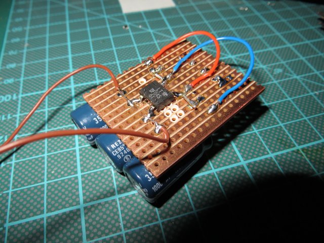
bridge rectifier
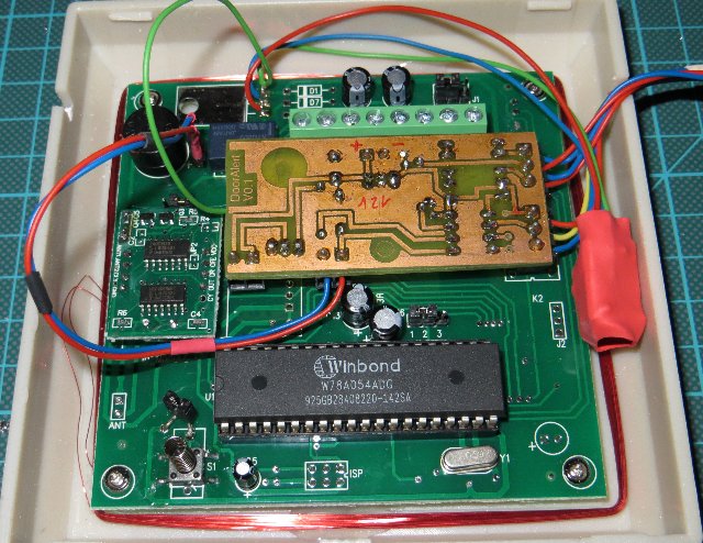
The controller board was created with Eagle in THT old school style (schematic + board: dooralarm – yes, I increased the diameter of the drill holes for the resistors and capacitors a little…). The brain of the board is an ATtiny45. The hall sensors part is played by a TLE4905L. It is quite easy to use – just connect Q to an input of the uC and use the internal pull up to create a clean logic 1 if no magnetic field is applied to the sensor – that’s all. In conjunction with that little neodymium cylinder magnet I got a detection range of 5..7 mm – far enough to sense the state of the door safely.
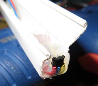
hot glue to keeps the sensor in place
The disarm hall sensor is placed inside the housing of the controller board. Just place a magnet on the housing – the alarm state is overridden – and the horn is off. The horn (piezo, 120dB@12V/0.2A) is controlled by a BUZ11 so I could extend the system easily by heavier loads.

schematic of the controller board
As I run out of pins (I kept the reset pin for easy programming) I used that funny way of driving the status LEDs with only one port pin… so don’t worry about that.
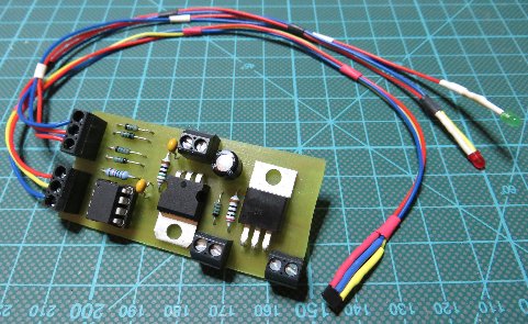
controller board
By accident I stumbled over the AD-2000M – a RFID/keypad door opener panel. I found a seller here in Germany (reduces shipping time a lot) that sold the device for a reasonable price: including 10 key chain tags and shipping only 12 € – nice. The devices arrived 2 days later – and I tried to understand the manual arrrgh! … in short:
- you can have 3 types of users
- activate with RFID tag only
- activate with RFID tag + 6 digit PIN
- 6 digit PIN only
- every user is identified by a unique 4 digit user id
- a user id can only be used with one type of user
(its not possible to use the same user id for a user with card or PIN only access)
The AD-2000M Rev. 3 works according to the following state machine:
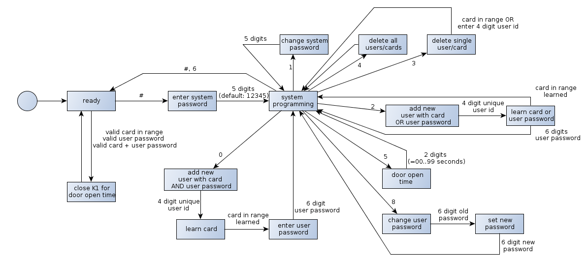
programming states ad2000-m rev 3.0
The AD2000-M is able to detect the RFID tags through the (wooden) door – a nice replacement for the hidden arm/disarm switch formed by bell knocking… good. The controller board also fits inside the housing of the device so no further enclosing is needed. Very good. During the first tests of the setup I recognized that the 7805 inside the AD2000-M creates an enormous heat. Bad. Reason: even in the „ready“- state the device draws 60mA (for what?!?) – makes ~0.4W power dissipation over the 7805… way to much over the time. I also disliked the idea having 2 7805 sitting around and wasting energy. The moment to use a very nice drop in replacement from TI: the PTH08080W. It comes in form of a ready to use wide input range step down regulator – just kick out the 7805, solder a resistor to the module (to select the desired output voltage – ~350 Ohm for 5V output) – and thats it… many thanks to TI for the samples! ***advertisement finished***
controller inside the ad2000-m
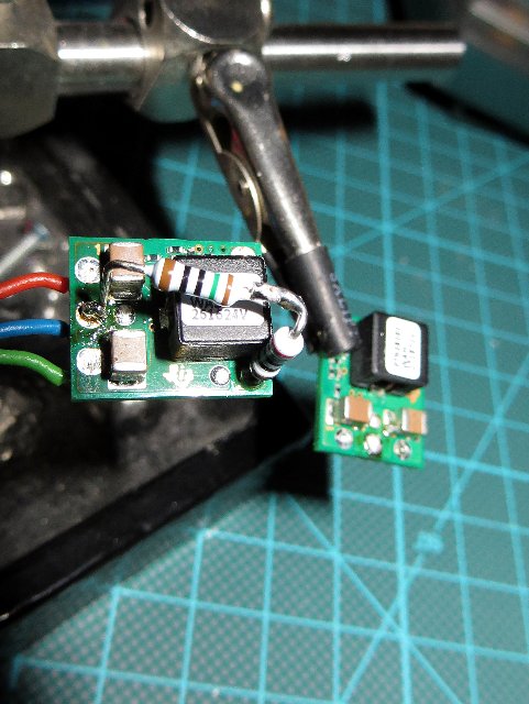
PTH08080W – drop in replacement
Note 1: the little jumper soldered to the via holes on the left side of the controller prevents me from the cover open alarm
Note 2: the shrink wire covered red blob contains the PTH08080W
Note 3: I used the two vias on the left side of the relay to connect my switch input (see schematic + board – input K1 +/-). The relay is switched on if the door opener is activated. I simply detect the state of the relay – voila – an RFID arm/disarm switch.
The alarm system is based on a simple state machine. If the system is armed by using a known identification token (RFID, PIN) and the door is opened a short sequence of pulses is given. After that, the horn sound continuously for 30, 45, 2x 60 seconds with little breaks. Finally the horn is deactivated – to protect my neighbors from screaming sounds during my holidays… (for easier drawing the „move from trigger-state-to-disarm“ transition is not shown).

states of the alarm system
The __LOCK-states are used for filtering bouncing contacts of the relay. To prevent a complete alarm cycle caused by a „hard knock“ against the door the system reverts to the armed state if the door is closed within the first 1.5 seconds. Programming the controller was straight forward… I just translated the state machine from the picture above. Since the code deals with a security device no optimization was applied – just easy to read and maintain code (dooralarm – firmware). Sorry! for not posting any picture of the finished system. But that would be like posting my bank cards PIN… That’s it.